Encoder Logic Circuit Diagram
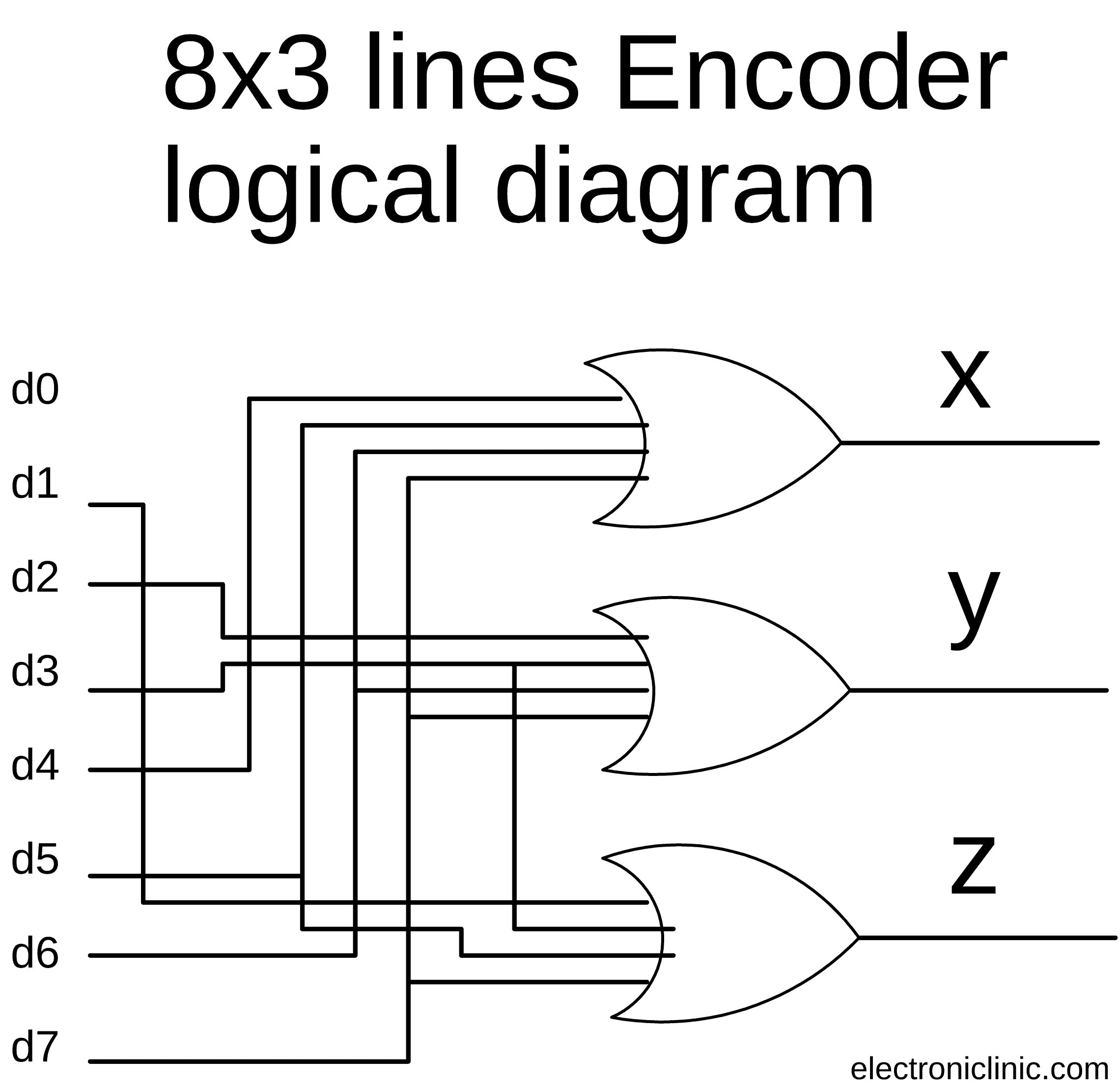
These or gates encode the eight inputs. The circuit diagram for this project can be build using the boolean expressions.
4 To 2 Encoder Circuit Diagram
Encoder Logic Circuit Diagram. Web the circuit that implements the inverse boolean function is called an encoder. Web the circuit that implements the inverse boolean function is called an encoder. Encoder combinational logic functions electronics textbook.
It Accepts 2 N Input And Produces Output In N Output Lines.
Web the 8 3 encoder circuit diagram consists of three logic gates: These or gates encode the eight inputs. Binary encoders basics working truth tables circuit diagrams.
The N Output Lines Generate The Binary Information Depending Upon 2^N Input Lines.
Encoder combinational logic functions electronics textbook. These gates are arranged in a particular order and perform the. Web coa encoders javatpoint.
That Is, If There Are 2 N Input Lines, And At Most Only One.
Web the circuit diagram of octal to binary encoder is shown in the following figure. Web the priority encoder is a combinational logic circuit that contains 2^n input lines and n output lines and represents the highest priority input among all the input lines. The circuit can be build using the basic not, and, and or gates.
In This Chapter, We Specify And Design Decoders And Encoders.
Web a general encoder's block diagram. Web the circuit that implements the inverse boolean function is called an encoder. Web get access to the latest hexadecimal to binary encoder circuit with truth table & circuit diagram prepared with cbse class 12 course curated by sangeeta komali on.
Web The Logic Circuit Diagram Of 4 × 2 Encoder.
Web an encoder is a combinational circuit that performs reverse function of a decoder. The circuit diagram for this project can be build using the boolean expressions. Web encoder has 2^n input lines and n output lines.

8 to 3 encoder circuit diagram

Solved Consider the circuit shown below, which contains a

Encoder Logic Diagram And Truth Table / Logic Diagram And Truth Table
Encoder Digital Logic Nancy Circuit

CircuitVerse priority encoder

4 To 2 Encoder Circuit Diagram

Pin on Electronic Circuit Diagrams

Electrical the circuit’s logic diagram of a (2bit binary to decimal
