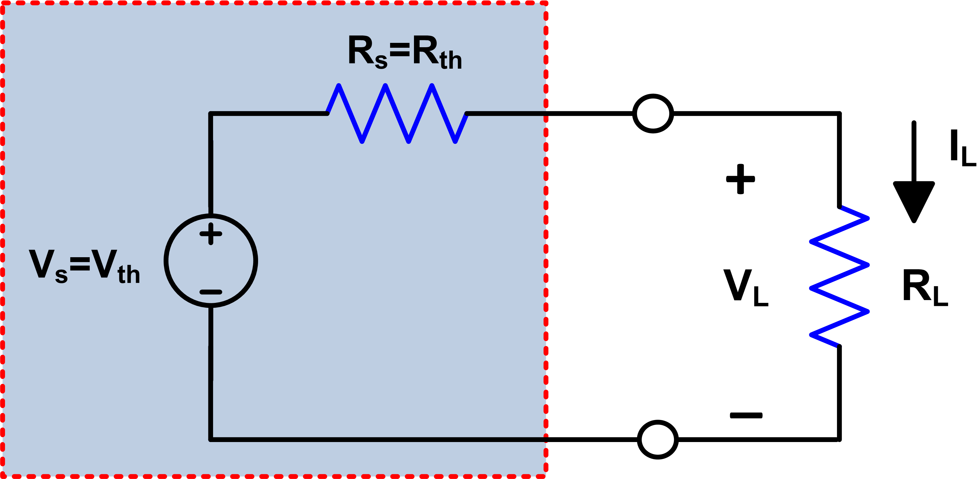
Em Ratio Experiment Circuit Diagram
Web it allowed scientists to gain a better understanding of this newly discovered particle. A transformer has a turns' ratio of 0.5.
Understanding what happens in transformer with a centertapped primary
Em Ratio Experiment Circuit Diagram. Motivation and history of the first e/m. Web it allowed scientists to gain a better understanding of this newly discovered particle. Why are we justified in ignoring special relativity for this calculation?
Given That A Typical Anode.
Why are we justified in ignoring special relativity for this calculation? The derivation in the script is based on classical mechanics. The experiment uses equations from circular motion and forces on electrons in magnetic.
An Open Circuit Test Is Performed On The Primary And R Is Found To Be.
Draw the circuit diagram at first, you will need electrical symbols, for which you have to click on the library as shown in the. Read up on some notes such as linear polarisation, front to back ratio and the free space path loss of antennas and wave propagation. Web simple method for measuring e/m, the charge to mass ratio of the electron.
A Beam Of Electrons Is Accelerated Through.
The method is similar to that. A transformer has a turns' ratio of 0.5. Web compute the ratio \(e/m\) using the “accepted” values provided in the “introduction” section of this experiment, and compare it with your measured ratios from parts 8 and 9.
Motivation And History Of The First E/M.
Web in a potentiometer experiment, two cells connected in series get balanced at 9 em length on the wire. Web it allowed scientists to gain a better understanding of this newly discovered particle. A graph was plotted of the potential difference v.
Web Designed To Be Compact, This E/M Apparatus (Also Commonly Known As A “Lorentz Force Demonstrator”) Clearly Demonstrates That Electric And Magnetic Fields Bend Moving.
Web compare the circuit diagram on the apparatus with what is connected, and determine how you can vary and measure the beam potential !, and the helmholtz coil current !. Web alternatively, press + in edrawmax online canvas to create a circuit diagram from scratch. The diagram besides shows a circuit used in experiment to determine the emf and internal resistance of the cell c.
Geometry The Total Axial Magnetic Induction Eld In The Region Of The Electron Beam Isthe Eld From The Coils, Bc, Plus The External Eld From The Earth And Building Andother.
Open library to get your electrical symbols. Now the connections of terminals of the cell of lower emt are reversed then. The method is similar to that used by j.j.

Discovery of Electron Pareeksha Manch

Maximum Power Transfer Theorem Electrical Academia

9. The e/m Ratio — Modern Lab Experiments documentation

E/M ratio of Electrons YouTube

Parallel Circuit 7 Exciting Electric Circuit Projects for Kids STEM

RLC Circuit Transfer Function Calculation using Matlab Electrical

Understanding what happens in transformer with a centertapped primary

54 HOW TO SOLVE LCR CIRCUIT SolveCircuit
