Electronic Watchdog Circuit Diagram
Web built around 555 timer ir beam falls directly on the ir sensors for this align transmitter and receiver ckt circuit diagram : After a bit of digging, i eventually found a working subassembly in.
Electronic Watchdog under Other Circuits 59229 Next.gr
Electronic Watchdog Circuit Diagram. Analog, digital, electrical, power, schematic diagrams How to configure watchdog timers of avr microcontroller atmega16 part 15 46. Analog, digital, electrical, power, schematic diagrams
The Transmitter Circuit Shown In Below Fig.1 Is Built Around Timer Ne555(U1),Which Is Wired As An Astable Multivibrator Producing A Frequency Of About.
Analog, digital, electrical, power, schematic diagrams Results page 7 about schematic. 3,787 likes · 1 talking about this.
38Khz Ir Transmitter Circuit The Receiver Circuit Is Shown In Fig.
Web introduction to watchdog timer hardwarebee. Web this circuit is under:, other circuits, a watchdog circuit diagram l59126 as figure: Web #1 while trying to lay this out this circuit in kicad, i realized this had to be the watchdog circuit.
3)• Mounted Face To Face.•.
2) •the circuit comprises a• transmitter & receiver unit• tracking device system. This is an electrical diagram template sharing platform allowing anyone to share your great electrical diagrams. Web i'm looking at building a watchdog that will power cycle my arduino (weather station) when it is not responding (my arduino gets a cmos lockup and doesn't respond.
It Comprises Ir Sensor Tsop1738 (Ir Rx1), Npn Transistor Bc548 (T1), Timer Ne555 (Ic2) And Some.
See more ideas about electronics circuit, circuit diagram, electronics projects. Receiver circuit transistor & npn transistor. Web hardware specifications ic 555, um66 i r transmitter receiver buzzer resistors capacitors transistors cables and connectors diodes pcb and breadboards led.
Web 1) •Used As Guard System In Entrance.
Two or more timers are sometimes cascaded to form a. Web a basic watchdog timer has a single timer stage which, upon timeout, typically will reset the cpu: How to configure watchdog timers of avr microcontroller atmega16 part 15 46.
3 Is A Logic Circuit Diagram Showing One Example Of A Pattern Matching Circuit Included In The Power Ic Of Fig.
When the operation of the circuit as long as the timing of the reset pulse to the cd4060, we. The purpose of the dogs is that they bark whenever a person. Web built around 555 timer ir beam falls directly on the ir sensors for this align transmitter and receiver ckt circuit diagram :
The Order That The Symbols Are Drawn In Relation To Each Other Will Correspond To The.
4 is a timing chart exemplarily showing. After a bit of digging, i eventually found a working subassembly in. The collection of electronic circuit diagram ( circuitdiagram.net ) fans page.
Web Of 26 Electronic Watch Dog Project Traditionally And Even Now Many People Have Pet Dogs Stationed At Their Entrance.
Web free download electrical templates online.

Telephone Watchdog Schematic Circuit Diagram

Arduino Watchdog With LM358 OpAmp Arduino, Amp, Arduino board

WatchDog Circuit 2.jpg 120.2K

555 Composition with Watchdog circuit under 555 Timer Circuits 57834

GitHub mattbornski/ArduinoWatchdogCircuit The current Arduino
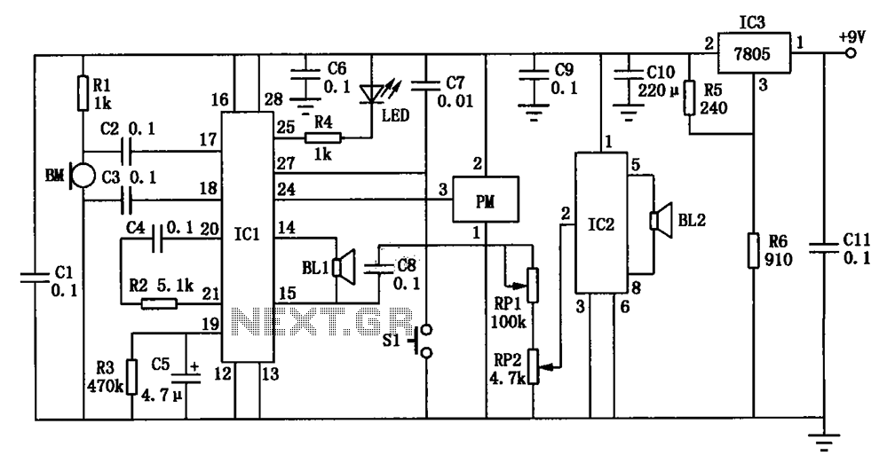
Electronic Watchdog under Other Circuits 59229 Next.gr

Simple Microprocessor power supply watchdog circuit Diagram

Electronic watchdog
